 Get Insights

How Frequency Range Shapes Ultrasound Performance Metrics in Imaging Systems
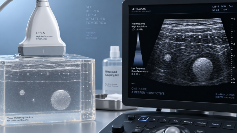
Frequency range sets the physical limits within which an ultrasound imaging system can balance detail, depth, contrast, and stability. A probe specified for higher frequencies is not automatically “better,” and a broad nominal bandwidth does not guarantee equally useful imaging across that band. The meaningful question is whether the transducer, beamformer, receive chain, image processing, and selected preset preserve diagnostic information at the frequencies needed for the intended acoustic path.
Ultrasound waves attenuate as they travel through tissue. Attenuation rises with frequency, so high-frequency energy loses usable amplitude more quickly than low-frequency energy. At the same time, shorter wavelengths support finer spatial discrimination. This creates the central trade-off: increasing frequency improves the potential to resolve small, shallow structures, while reducing the depth at which echoes remain strong enough for a stable image.
Frequency establishes the depth-resolution trade-off
Axial resolution depends primarily on spatial pulse length. A short pulse occupies less distance along the beam axis, allowing two reflectors located one behind the other to be displayed separately. Higher center frequencies support shorter wavelengths and, when paired with sufficient bandwidth and pulse damping, shorter pulses. This is why superficial structures such as tendons, small vessels, nerves, thyroid tissue, and near-field soft tissue are commonly examined with high-frequency linear arrays.
That relationship is incomplete without bandwidth. Two probes with a similar nominal center frequency can produce different axial resolution because pulse duration depends on the transmitted waveform and the transducer’s effective bandwidth. A narrowband element tends to ring longer after excitation. Its echoes contain more cycles, increasing spatial pulse length even if its labeled frequency is high. A broadband element with effective backing and damping can produce a shorter pulse, preserving separation between closely spaced interfaces.
Lateral resolution follows a different path. It is governed by beam width, which changes with aperture, focusing, frequency, element pitch, and depth. A higher frequency generally permits a narrower beam for a given aperture, but the advantage is strongest near the focal region. Away from that region, the beam diverges and lateral detail degrades. A system that shows excellent line separation in a shallow focal zone may therefore offer less consistent performance at the deepest portion of the image.
Penetration is an image-quality threshold, not a depth setting
Most systems allow the displayed field of view to extend well beyond the depth at which clinically useful information remains. A depth scale only defines the reconstructed image window. Penetration should instead be judged by whether expected structures remain distinguishable from noise, reverberation, side-lobe clutter, and electronic noise at the required depth.
Frequency-dependent attenuation is often described with a simple proportional model: attenuation increases with both propagation distance and frequency. The actual loss varies with tissue composition, intervening fat, fibrous layers, fluid, gas, bone boundaries, and the angle of incidence. A preset that performs well through a relatively uniform path may fail when energy crosses heterogeneous layers that scatter or refract the beam. This distinction matters when comparing images acquired on different test objects. A uniform phantom can expose resolution limits, yet it may underrepresent the clutter and attenuation encountered in a heterogeneous acoustic path.
Transmit power, receiver gain, time-gain compensation, persistence, and post-processing can make a deeper region look brighter. None of those controls recreates signal that was never received. Excessive gain elevates noise and clutter along with weak echoes; aggressive speckle reduction can suppress fine texture and blur small boundaries; persistence can make a still image appear cleaner while obscuring motion or reducing temporal responsiveness. For penetration claims, raw or minimally processed image review is more informative than a heavily optimized demonstration preset.
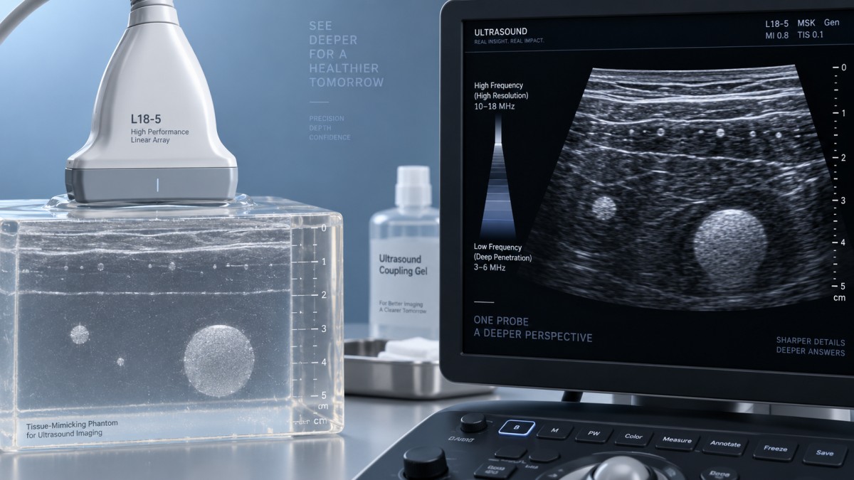
Signal-to-noise ratio changes across the band
The useful performance of a frequency range is shaped by transmit efficiency and receive sensitivity, not by frequency alone. Piezoelectric or capacitive elements convert electrical excitation into acoustic pressure with an efficiency that varies across their operating band. Matching layers, backing material, lens construction, cable losses, and impedance matching influence how much energy enters the patient and how much returning energy reaches the receiver.
A transducer may advertise a wide range while producing its strongest sensitivity near a narrower center region. At the band edges, transmit pressure can decline, receive sensitivity can fall, and the beam pattern can change. The displayed image may still be acceptable, but a comparison based on the full labeled range can overstate equivalence between probes. Frequency-response curves, pulse spectra, or standardized phantom images acquired at matched depths reveal more than a single range printed on a datasheet.
Electronic noise has a larger effect when returning echoes are weak. This is particularly visible at high frequencies and deeper targets, where tissue attenuation reduces echo amplitude before it reaches the elements. The system may compensate visually with gain, but the signal-to-noise ratio remains limited. Conversely, a low-frequency probe can maintain signal at depth while sacrificing the fine edge definition that makes small targets conspicuous. A useful image is therefore not the one with the most visible speckle or the highest apparent sharpness; it is the one where relevant interfaces and low-contrast structures remain separable with stable contrast.
Resolution measurements need controlled geometry
Resolution specifications are easily misread when the test geometry is not stated. Axial and lateral resolution should be measured separately, at stated depths, with stated focal settings and a known target configuration. Wire targets, filament targets, or closely spaced reflectors can demonstrate point-spread behavior, but their results depend on alignment. A slight target-angle error broadens a reflected response and may appear to reduce resolution even when the beam is unchanged.
For lateral resolution, focal depth must be recorded because the narrowest beam is normally found around the focal zone. Dynamic receive focusing improves beam control over a broader depth range, but it does not make resolution uniform from skin line to far field. Multi-focus transmission can improve detail over several zones, although it reduces frame rate because more transmit events are required for each image frame. A still image from a multi-focus mode should not be compared directly with a single-focus image when real-time motion performance matters.
Elevation-plane resolution also deserves attention. A conventional one-dimensional array controls the beam actively in the azimuthal plane, while slice thickness in the elevation plane is often set by fixed lens geometry or acoustic focusing. Structures outside the intended imaging plane can contribute partial-volume artifacts. Frequency affects this behavior, but it does not eliminate it. A probe with strong in-plane detail may still display blurred or misleading anatomy when section thickness is large relative to the structure being assessed.
Frequency selection changes Doppler behavior
In Doppler imaging, the frequency shift increases with transmit frequency and the component of blood velocity aligned with the beam. A higher-frequency probe can therefore produce a larger shift for the same flow condition, improving sensitivity to slow flow when the vessel is superficial and attenuation is manageable. Yet the higher shift also consumes more of the available sampling bandwidth, increasing the risk of aliasing in pulsed-wave Doppler at a given pulse repetition frequency.
Depth imposes a second limit. Pulse repetition frequency is constrained by listening time: the system must wait for echoes from the selected depth before issuing the next pulse. At greater depths, the allowable pulse repetition frequency falls, narrowing the unambiguous Doppler velocity range. Higher transmit frequency, deeper sampling, and fast flow are therefore a difficult combination. Lowering the Doppler frequency, shifting the baseline, increasing the velocity scale when permitted, or using continuous-wave Doppler for appropriate applications changes the trade-off, but each adjustment affects information content differently.
Color Doppler and power Doppler are also vulnerable to frequency-related choices. High-frequency settings can reveal weak flow in superficial vessels, but wall filters, packet length, motion, and clutter suppression may dominate the result. A vessel that appears devoid of flow may reflect poor acoustic access, excessive wall filtering, low color priority, an unfavorable insonation angle, or motion artifact rather than a true absence of flow. Frequency should be evaluated alongside the complete Doppler preset, not as an isolated probe attribute.
Nominal range does not describe a complete imaging system
Probe geometry shapes how frequency is deployed. Linear arrays maintain a rectangular near-field footprint and are suited to shallow, accessible regions. Curvilinear arrays widen their field with depth and are commonly paired with lower frequencies to support deeper paths. Phased arrays use a small acoustic footprint and electronic steering, often prioritizing access through narrow windows over broad near-field coverage. Comparing their frequency ranges without considering aperture and beam steering produces misleading conclusions.
Element pitch becomes more demanding as operating frequency rises. If the spacing between elements is too large relative to wavelength, steering can create grating lobes: secondary beams that place echoes at incorrect lateral locations. A system may limit steering angle, reduce aperture, or alter frequency to control this behavior. These design choices influence image uniformity and frame rate. High frequency alone cannot be interpreted as a direct measure of beam quality.
Near-field performance is another area where a simple depth-versus-frequency model fails. Superficial imaging can be degraded by transducer ring-down, dead zone, inadequate contact, a thick protective cover, or an unsuitable stand-off layer. High-frequency probes are especially sensitive to small changes in coupling because their short wavelengths interact strongly with thin gaps and surface irregularities. Air at the skin interface remains highly reflective, so gel application and probe contact affect repeatability more than modest gain adjustments.
Comparing systems without confounding the result
A defensible comparison holds the acoustic task constant. Use the same target depth, probe orientation, output setting where available, focal strategy, dynamic range, and image-processing level. Record the selected transmit frequency rather than only the probe model. Several systems choose frequencies automatically within a nominal probe band, and the selected value may shift when the preset, harmonic mode, imaging depth, or tissue optimization changes.
Tissue harmonic imaging requires separate interpretation. It receives energy near a harmonic frequency generated during nonlinear propagation, often reducing near-field clutter and improving contrast in selected conditions. The apparent improvement does not mean the probe has simply become a higher-frequency fundamental imager. Harmonic signals are weaker in the near field, may be limited at substantial depth, and depend on transmit frequency, acoustic output, tissue path, and receive filtering. Comparing harmonic and fundamental images as though they represent the same frequency condition can distort conclusions about penetration and resolution.
Documenting environmental and configuration details prevents later disputes. Phantom temperature, probe surface condition, cable strain, preset revision, software version, compression settings, and display scaling can alter observed results. A damaged matching layer or lens may reduce coupling and introduce local dropouts. Intermittent connector faults can resemble random noise or element failure. Before assigning a discrepancy to frequency performance, inspect uniformity across the aperture and repeat the acquisition with controlled contact and a known reference target.
Interpreting the frequency range as usable operating territory
The most informative specification is a frequency range tied to evidence: resolution at defined depths, contrast visibility under controlled attenuation, beam uniformity across the field, Doppler response under stated flow conditions, and frame-rate behavior with the required focus settings. A broad range provides flexibility only when those measurements remain credible across the intended portion of the band.
Frequency should therefore be treated as an operating variable that redistributes performance rather than a headline number. Higher settings shift capability toward superficial detail and Doppler shift sensitivity; lower settings preserve signal through deeper paths; intermediate settings often provide the most stable compromise when target depth and tissue attenuation are uncertain. The resulting image quality comes from the entire acoustic and signal-processing chain, measured under conditions that resemble the task rather than under a single optimized display state.
Recommended News
- 2026.10.15Medical Packaging Heat Seal Testing: Seal Strength vs. Seal Integrity TestsDr. Julian Rossi (RehabTech Specialist)
- 2026.10.14Clinic Supplier Comparison: Evaluating Cost, Delivery Reliability, and SupportDr. Alistair Thorne (Senior Biomedical Engineer)
- 2026.10.13Engineering Performance Testing Services: Evaluating Test Methods and AccuracyDr. Alistair Thorne (Senior Biomedical Engineer)
The VitalSync Intelligence Brief
Receive daily deep-dives into MedTech innovations and regulatory shifts.